Wednesday 12 October 2011

07 - Making the Rigging Blocks - Part 2


In the last post, I described how I scaled and designed a template for the blocks. In this post, I'll describe the fabrication details for the two scale sizes that I eventually decided would be sufficient to represent the range of seven blocks on the full-size vessel. (Jenson listed 87 blocks, ranging in size from 6 inches to 13 inches.)

Having generated templates for the two sizes, these were then pasted on 1/4" X 1/8" strips of boxwood. For the smaller blocks, the long dimension was positioned across the strip; for the larger block, the long dimension was positioned lengthwise. The picture below shows some of the smaller blocks cut from the strip, ready for shaping.

Small block template applied to boxwood strip, ready for shaping.

Once separated, I used the Dremel tool with a mini-sanding drum to rough out the shape to the template.
Deremel tool, table-mounted with sanding drum. 

With a little manual sanding, the basic shape of the block was arrived at without too much difficulty.

Shaped boxwood block, ready for detailing. 

At this point, another decision was required. On the Bluenose II, the modern-style blocks do not have external stropping. This is in contrast to older blocks, which had an external band (or strap) to both hold the block together as well as attach the eyes (used to secure other hardware such as hooks, shackles,and thimbles to the block). Since I wasn't prepared to make a "built-up" block with internal hardware, the external stropping approach seemed the obvious way to go.

Besides, I think the stropping adds to the visual effect - without it, the blocks look a little bland.

(After build note: Although at this point in the build I was still intending to configure the model as the
Bluenose II, in the end, I decided to fit it out as the original Bluenose and so the stropped blocks look just right.)

After some experimentation, I settled on the following method to produce the blocks. First, drill a hole at one end of the block to represent the sheave, through which the rigging will run.

Drilling the sheave "hole".

Next, using a mini-rasp, add a grove along the edge of the block on both sides to further define the sheave.

  Detailing the sheave.

Finally, cut a grove on each side of the block to hold the stropping.

Cutting grove for stropping.

With these details done for all blocks, I started on the stropping. Twenty-seven gauge wire was used; anything smaller was unlikely to retain its shape when formed into eyes and subjected to the strains of rigging. Eyes were formed using a suitably size rod; in this case 1/16". A hole drilled into the building board held the rod and allowed me to form the eye. The following series of pictures are self-explanatory.

Rod and wire, ready to form an eye.

Two loops to form the eye.

Wire stropping applied to the block.


Securing the stropping.

With the stropping wire twisted secure and the excess cut off, the block is essentially finished. In those instances where an eye is needed at both ends, a loop of wire will be inserted at the other end.

Finished block. Tried an ink spot to simulate sheave axle. (Not applied to final versions.)

A dip in clear polyurethane was the final step.

Complete blocks dipped in urethane hanging to dry. 

For double and triple sheave blocks, wood strips were glued together prior to shaping.

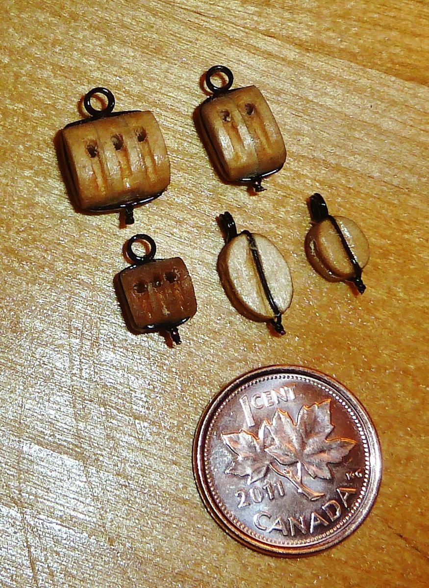
Completed one, two and three sheave large blocks and
single and three sheave small blocks.
The following pictures show a set of blocks assembled on one of the jibs for a test fit.

Single sheave small block.

Double sheave small blocks.

Next post: the sails.


Thursday 29 September 2011

06 - Making the Rigging Blocks - Part 1

One of the first items that I undertook to try and reproduce to an appropriate scale appearance were the rigging blocks that were on the original model. In fact, to refer to them as "blocks" is an overstatement! They were merely round hardwood bobbins with a single hole and a groove around the circumference - there was no way that the rigging lines could be run through them to represent proper blocks.

Original model blocks.
(Note: the two-hole versions were used to represent 'deadeyes'.)

The first thing I did was to ascertain how many blocks were used on the full-scale ship, as well as their sizes. Fortunately, Jenson concisely summarized the utilization of blocks on the Bluenose II (and their sizes) in the extract below. Notice that the size ranges from 6 inches to 13 inches, with the majority being single sheave but there are also a few double- and triple-sheave blocks as well.

Listing of rigging blocks used on the Bluenose II.

I was a little surprised at the range of sizes (6, 7, 8, 9, 10, 12 and 13 inches) and so the first decision was whether to try and replicate all the sizes in 1:44 scale. Didn't take me long to figure that most people would be hard pressed to distinguish between 0.136" and 0.205" (the full scale dimensions of 6" and 9" respectively) or 0.227" and 0.295 (full scale dimension of 10" and 13" respectively), particularly if the items weren't located side-by-side. So I elected to go with two sizes only, representing blocks in the 6" to 9" range with one size and blocks in the 10" to 13" range with a second size.

Next, I had to determine what to use as the source material. Seeing as the full-scale block is made of hardwood (usually oak), I initially tried to make the model blocks out of this type of wood.

Actual Bluenose II oak block.

Unfortunately, hardwood proved to be too difficult to shape, especially when dealing with something this small - and my limited skill level! Research on the internet revealed that boxwood was a good candidate material, and fortunately the craft store Michael's was a good source. I selected strips 1/4 inch wide by 1/8" thick. These dimensions would allow me to make two sizes of blocks, depending on whether the long dimension of the block was across the strip or parallel to the long dimension.

Now I had to determine the proper shape for the blocks. Having visited the Fisheries Museum of the Atlantic in Lunenburg, Nova Scotia (http://museum.gov.ns.ca/fma/en/home/default.aspx) several years ago, I had a photograph of one of the original Bluenose I blocks at my disposal.

Bluenose 1 block.
(Note pen for size measurement - didn't have a ruler with me on the day!)


I then inserted the picture on a page in Microsoft Word and using the drawing tools, outlined the edge of the block.
Outline shape in red using MS Word drawing tools.


Now I could scale this shape to whatever size I needed.

Block outline shape moved to the side.

Now it was a fairly simple matter to copy the shape to a blank MS Word page, draw several pairs of parallel lines a 1/4 inch apart and then size and position the block shapes accordingly.
Lines drawn 1/4"apart in MS Word.
 (Note: Page was scaled to 200% - hence the screen ruler reads 0.5 inch. versus 0.25 inch.)


Large and small block shapes added to the page.
(Some additional detail  added to make the outline more representative.)

Showing how the block shapes were inserted between the lines.

To make the production template, I merely copied and repeated each of the shapes on their own sets of parallel lines.

Production templates, ready to be cut and glued to boxwood strips.


Here is the template glued to one of the wooden strips and a stack of blocks cut from the strip and ready for shaping.

Block template applied to wood strips, with some already cut off, ready for shaping.

In Part B, I'll continue with the fabrication of the blocks.

Wednesday 28 September 2011

05 - Refurbishing the deck planking.

Well, I'm finally back at it. No, I didn't spend all of the last six months down in Florida - just five weeks or so! The rest of the time, I've been enjoying our summer. But now that we're officially into fall, time to pick up where I left off. In fact, I'm going to skip a few of the items that I've already done some work on - I'll get back to them in future posts - and bring you up to speed on the deck refurbishment in the meantime.

To start with, the original decking was very poorly executed. The manufacturer used a single piece of what looked like laminated particle board. This was then grooved to simulate planking. Unfortunately, the result was imitation planking that was much wider than the scale would indicate, and the router grooves were far too wide. In addition, the planking was parallel for the total length of the deck, whereas the real planking was curved at the aft section.

Original model decking. (Marks were made during removal of deck furniture.)

As noted in a previous post, I made use of cherry wood strips sourced at Lee Valley. I initially purchased 1/8 inch strips (which would have more closely matched the full-scale width of 5-6 inches) but decided that they would look a little small. So instead, I chose to use 3/16 inch, which equates to a full-scale plank width of 8-10 inches.

Various sizes of cherry wood strips (1/8, 3/16 & 1/4 inch x 24 inch).

Having experimented a bit, I chose to stain the strips and blacken the edges to highlight the planking, once installed. The stain you use is a personal choice but I attempted to match the plank colouring of the Bluenose II. However, it is difficult to stain cherry to match oak, and in the absence of first hand observation, have no way of knowing how close I came. (And since the original decking of the Bluenose II no longer exists, it having been relegated to a wood chipper during the recent "renovation", we'll never know!)

To save time, I bundled 20-30 stained strips together and used spring clamps to hold them fast.

Cherry strips bundle and clamps.

Once clamped, I lightly sanded the bundled edges and them used a permanent marker to paint the edges black.
Using a permanent marker to blacken the edges of the strips.
Once the strips were dry, I glued a starting strip down the centreline and then worked outwards to either side of the ship. In the forward section, the planks are installed parallel to the centreline, whereas in the aft section, they are curved parallel to the sides.

Installing cherry wood strips on forward deck.

Before and after sanding of cheery strips.

Once all the strips were installed, I elected to simulate end joints and peg-ends randomly over the deck. There was no indication of full-scale plank lengths in the Jensen book. (I could have cut strips to various lengths prior to gluing them to the deck but felt that this was an unnecessary complication and could be simulated just as effectively.)  To aid in making the simulated peg ends, I fabricated a little template jig to locate the peg-end holes on either side of the simulated joint. The joint itself was made by using a metal awl to scribe a line across the strip wherever a simulated joint was to be created. The awl was then used to pierce the strip on either side of the scribe to simulate peg-ends.
Jig for locating peg-end holes on either side of the simulated plank joint.
Once the deck covering was complete, a light sanding was in order. This necessitated another coat of stain to make the surface uniform in colour. I then sealed the deck with a coat of clear polyurethane; I've used gloss to date but suspect that semi-gloss, or even matte, might be more appropriate.

Completed deck. Note the curved planking on the aft section of the deck.

Next time, I'll try and cover some of the items I've already fabricated.

04 - On Vacation

As indicated before, nothing new to report on the Bluenose II rebuild, seeing as we're enjoying non-stop sun here in SW Florida. However, thought I'd share a couple of snapshots from what the locals like to remind you each morning is "another day in paradise"!

Can quibble with definition of 'paradise" but for many people there is no argument that the sugar sand of the beaches probably beats the dirty snow of late winter any time!

Fort Myers Beach.

Fort Myers Beach pier.

Sunset, Fort Myers Beach.

Fort Myers Beach.

The end of another 'day in paradise'.

Till next time...

Sunday 6 March 2011

03 - Scale Determinations

Before starting to fabricate any part of the model, it was necessary to determine the actual scale of the model I had acquired. There was no indication of scale on the packaging, so I used the measurements given by Jenson in his book for key aspects of the full-size Bluenose II and then calculated various scale dimensions for different scale ratios. It became apparent that not all dimensions of the model were consistent with a single scale ratio. The chart below shows my findings:

Comparison chart of full size, model and theoretical dimensions. 
(Used to determine model scale ratio.)

The yellow column records the full-size measurement (from Jenson) and the red column details the corresponding measurements from the model. The next four columns are the theoretical scale measurements for the following ratios: 1:40, 1:44, 1:48 and 1:60. While no single ratio matched the model dimensions exactly, the scale ratio of 1:44 (green column) came closest, and that is what I have chosen for this model. Not a usual scale as far as I can determine but I'm sure no one will notice!

With this ratio established, I undertook to generate a spreadsheet to allow for easy determination of scale dimensions without the need to perform individual calculations each time I wanted to make a measurement. Here is the chart that I'm using - a real time saver. The chart is divided into two parts: the upper portion provides scale conversion for full-size measurements in inches from 1" to 60", and the lower portion provides conversion for full-size measurements in feet from 6' to 97'. Thus, any full-size dimension up to 102 feet (by combining data from both portions of the chart) can quickly be converted to a scale dimension in inches. Other than overall length of the boat, this will accommodate every possible measurement that will be encountered when modeling the Bluenose II.

Scale conversion chart for scale ratio of 1 to 44.

Another scale requirement is the need to ascertain the correct size of ropes used in the standing and running rigging. Since the sizes of wire and cable of the appropriate dimensions for this model are usually differentiated by "gauge" number, it was also necessary to develop a scale conversion chart for this purpose. (Wire, manila and polypropylene ropes used on the Bluenose II range in diameter from 3/4 to 3-1/4 inches.) With information sourced on the Internet, felt this chart afforded the best display of the required information:

Wire gauge chart. 

Note that the actual dimensions of the diameter of model-size rope and twine will be in the order of 0.018 to 0.074 inches, or 26 to 15 gauge.

Next post, I will document my use of this information to fabricate my first model components - rigging blocks to replace the round "bobins" on the original model.

But not until I'm back from Florida...

Saturday 5 March 2011

02 - Tools and Sources

I have a little time before leaving for Florida, so will provide a bit of background information before delving into the actual model construction in a month or so.

First of all, I have access to my Taig model lathe (from Lee Valley Tools - more on this company later), which I have used in the past to machine model steam engines from casting kits. For those who may be interested, here is a web site I created to chronicle my early efforts at fabricating model steam engines using the Taig lathe: http://www3.sympatico.ca/tflydon/ .

\
Taig model lathe, configured for metal turning.

While not critical to working on this model, it does come in handy; thus far, I've used it to taper the masts. However, this could likely be accomplished using a drill fixed in a clamp, so the lathe is a "nice-to-have" when working with wood.

The tool that I DO find indispensable, though, is a "Dremel" tool, or its equivalent. To increase its utility, I made a very simple stand to enable its use as a table sander.

Here is the basic table, with an appropriate length of plastic pipe epoxied to it. (I was fortunate to have a piece the right diameter hanging about.) After drilling a hole just slightly larger than the miniature drum sander that I was going to use, I enlarged the underside to accept the plastic pipe and epoxied it in. Cutting out cooling slots and matching the case profile for things like the on/off switch completed the job.

Here is the result, and alongside it is the Craftsman-brand "Dremel" tool that I use.

Table adapter to use 'Dremel' tool as vertical sander.

Here the drill is inserted in the housing (a hose clamp provides the requisite holding force):

'Dremel' tool inserted in table adapter.

With a small drum sander inserted in the drill, you now have a model-sized drum sander. It lacks the up-and-down cycling of a commercial version but short of that, works just as well. You can adjust the height of the drum relative to the table surface by means of either the hose clamp or the drill's chuck/collet. (The paper shield you see glued to the table was put there in an effort to stop small pieces from being kicked off, never to be seen again!)

Mini drum sander mounted in table adapter.

Other than normal modeling knives, a pin vise and some numbered drills (in the #50 to #70 range) are the only essential tools I've used thus far. A good source for a reasonably priced pin vise is Lee Valley Tools  (http://www.leevalley.com/en/home.aspx);  this vice has the added benefit of including a set of 12 numbered drills. (If more sizes are needed, Lee Valley has sets for sale.)

Pin vise and numbered drills.

While I'm talking about Lee Valley Tools, I should point out that they are a source of materials as well. In particular, they sell a range of cherry veneer strips, which are invaluable for model ship builders. For my purposes, a tube of 24" X 3/16" strips (about 225 pieces) will more than meet my needs, although 1/8" and 1/4" wide strips are also available.

Cherry wood strips - 1/8, 3/16 and 1/4 inch width.

Finally, an invaluable source of information on the actual Bluenose II is the illustrated manual by L.B. Jenson, which includes measured drawings. With luck, you may be able to find a copy at your local library (I was), but I was also fortunate enough to catch sight of a copy at Lee Valley - needless to say, I purchased it on the spot.

Book of measured drawings of the Bluenose II by LB Jenson.

Given the drawings in this book and access to a printer/copier, I was able to enlarge (by 182%) the drawings to exactly match the size of my model. Since Jenson provides plan and side views of the deck furnishings, it should be possible to quite accurately replicate the real ship.

Copies of drawings from LB Jenson book, enlarged to match  the model's dimensions.

Notice that there are some differences between the Bluenose II (as depicted in the drawings) and the original Bluenose (furnishings from the model sitting on top); in particular, the size of the deck house. 

As it stands now, I plan to convert the model to the Bluenose II variant but that may change as the project proceeds.

Till the next time...